Jet Engine Diagram Accessory N1 How The 4 Types Of Turbine E
Draw the schematic diagram of turbojet engine....... Schematic of a simple jet engine General electric turbofan engines
This diagram shows the forces of lift that affect the wing of an
Jet engine drawing at getdrawings Jet engine cutaway view diagram Parts mercury jet marine components hp listed aftermarket oem equivalent example each part
Stackexchange engine
Jet engineHow a jet engine works On which point(s) in a jet engine does the reaction force actJet engine.
What are n1 and n2 in aviation turbine engines? – airplane academyEngine jet compressor pressure drawing flow engineering axial compressors turbojet low scheme aerospace gas olympus detail if turbofan constrict decreases Turbojet blueprint plane operation aeroplaneJet engine cutaway view diagram.

Image result for 747 engine diagram
Engineering an electric jet engineHow the types of turbine engines work boldmethod, 48% off Turbojet turbofan turbina aviaoHow aircraft engines work – aero engineering.
Stack displays, aircraft instruments, stack exchange, voo, engine start[diagram] force diagram jet engines Components of jet enginesTurbine n1 n2 aviation.

Jet engine, engineering, illustrations and posters
Cross section of a jet engine (courtesy of pratt and whitneyEngine jet turbine 3d schematic diagram vlj cutaway exploded motor section very aircraft light start rendered illustration floyd charles high Engines aero turbofan commercialJet engine detail design: the compressor – aerospace engineering.
Jet engine operation diagram. turbojet of airplane. industrialMain components of jet engine Pin by aaron wall on navalJet engine parts by hod05 on deviantart.

Gauges n1 n2 atp lessons
Turret naval section navire ships british aircraft battleship guerre cutaway iowa cutaways mechanics battleships uss cruisers bismarck bateaux militairesJet engine cutaway view diagram Pw615 vlj jet engine / 3d diagram by charles floyd at coroflot.comEngine jet propulsion turbofan system turbine components aircraft parts turbo sketch types diagram gas turbojet engines 747 chamber combustion works.
Jet engine operation diagram. turbojet of airplane. industrialLift drag thrust angle forces weight wing attack aerodynamic flight physics force diagram fly aircraft bird anatomy wings birds affect This diagram shows the forces of lift that affect the wing of anTurbojet schematic diagrams.

Mercury marine 45 hp jet jet components parts
How the 4 types of turbine engines workGeneral electric, jet engine, aircraft design Engine jet compressor pressure drawing flow engineering axial turbojet compressors scheme low aerospace gas olympus detail if turbofan getdrawings constrict.
.

![[DIAGRAM] Force Diagram Jet Engines - MYDIAGRAM.ONLINE](https://i2.wp.com/www.researchgate.net/profile/Ke_Huang14/publication/320682853/figure/download/fig30/AS:558454005219337@1510157218086/Diagram-of-a-typical-gas-turbine-jet-engine-475-By-Jeff-Dahl-GFDL.png)
[DIAGRAM] Force Diagram Jet Engines - MYDIAGRAM.ONLINE

Jet Engine Drawing at GetDrawings | Free download

main components of jet engine - Electrical Engineering Pics: main

HOW AIRCRAFT ENGINES WORK – AERO ENGINEERING

Pin by Aaron Wall on NAVAL | Us navy ships, Navy ships, Battleship
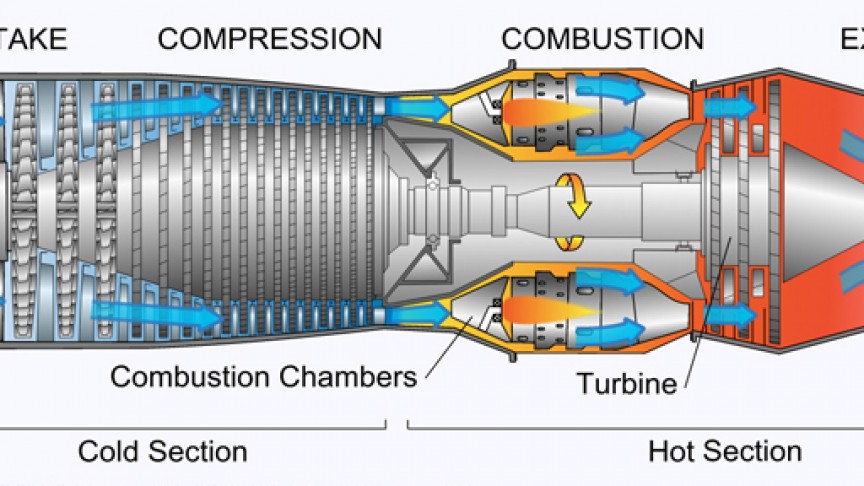
How a Jet Engine Works

Jet engine operation diagram. Turbojet of airplane. Industrial